Anthony-JohnsonConsulting Engineer Ltd
Selected work

Drawings and design from live projects.

A small selection of recent commissions — each showing the survey, calculation and detailing that sits behind a finished scheme. Drawings and figures are taken directly from the issued design packages.

Project 01 — Conversion & foundations
North Wootton, King's Lynn January 2026

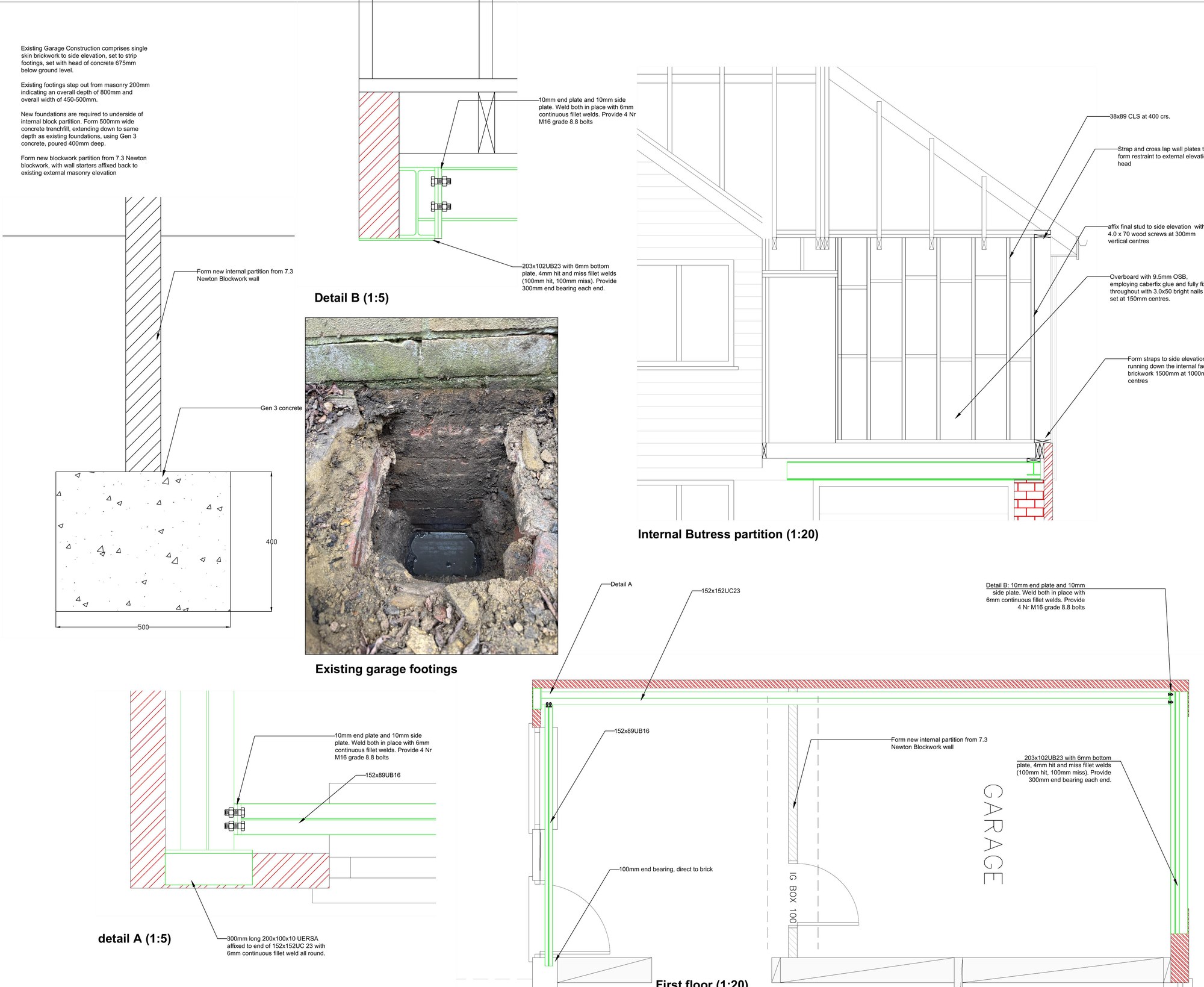
Garage-to-dwelling conversion with cantilever foundations

Geotechnical investigation and structural design enabling a single-storey garage to be converted to residential use, including a cantilever foundation cast hard against a neighbouring party wall.

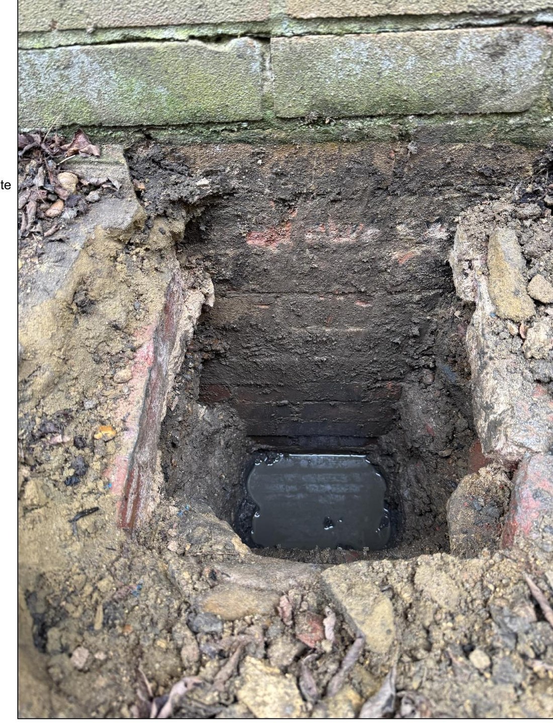
The garage forms the side structure to an existing single-storey property, and the client wished to convert it to habitable space. Three boreholes and trial pits were sunk to prove the ground and expose the neighbour's existing footings, finding coarse sands and gravels — likely river terrace deposits — over which traditional foundations could be safely formed.

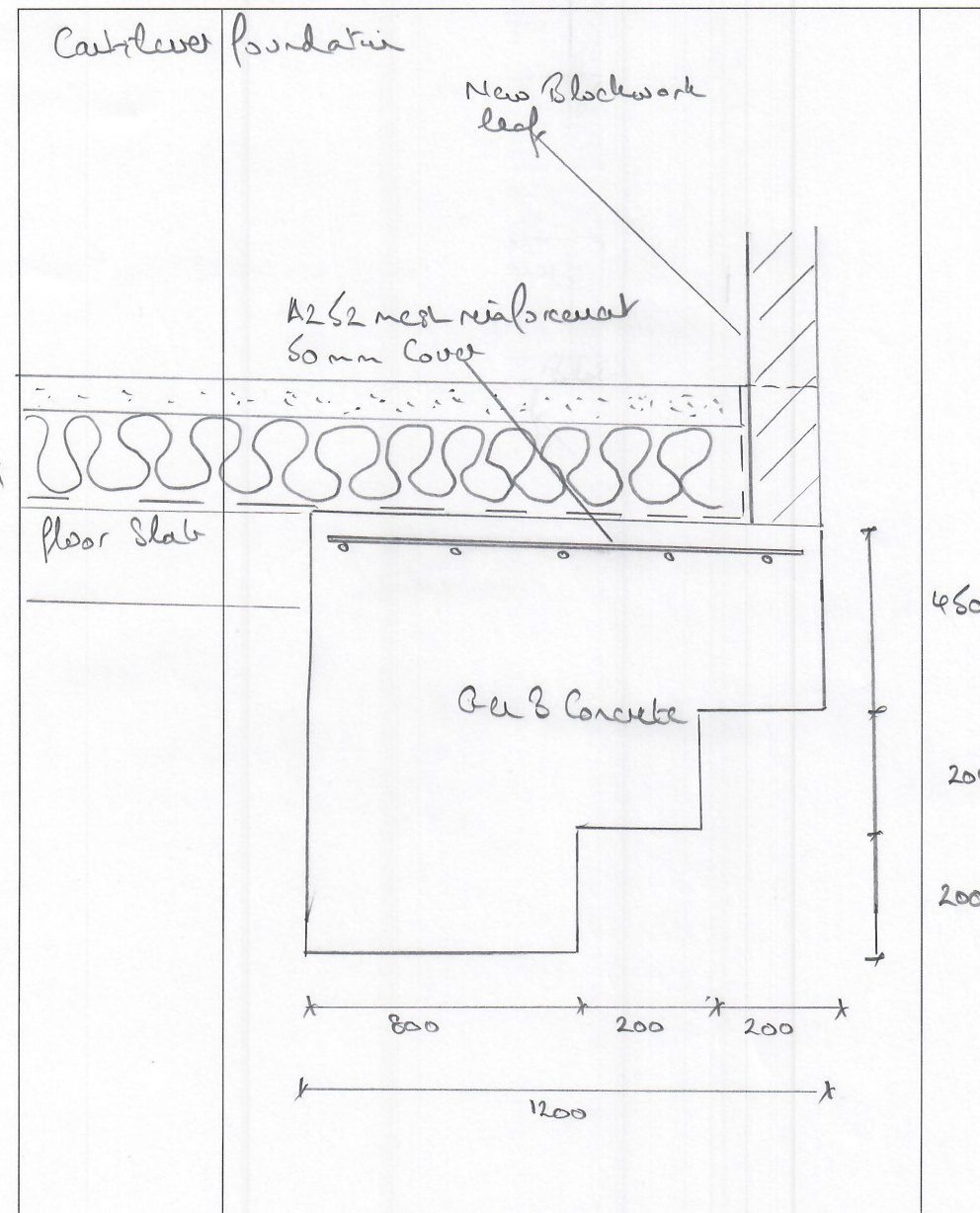
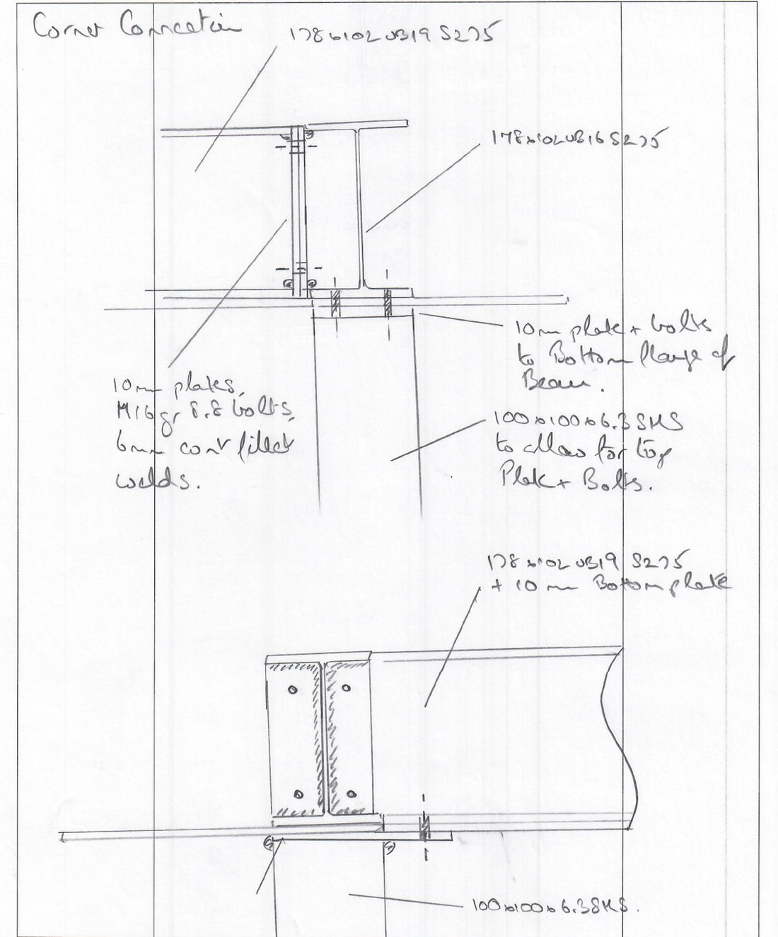
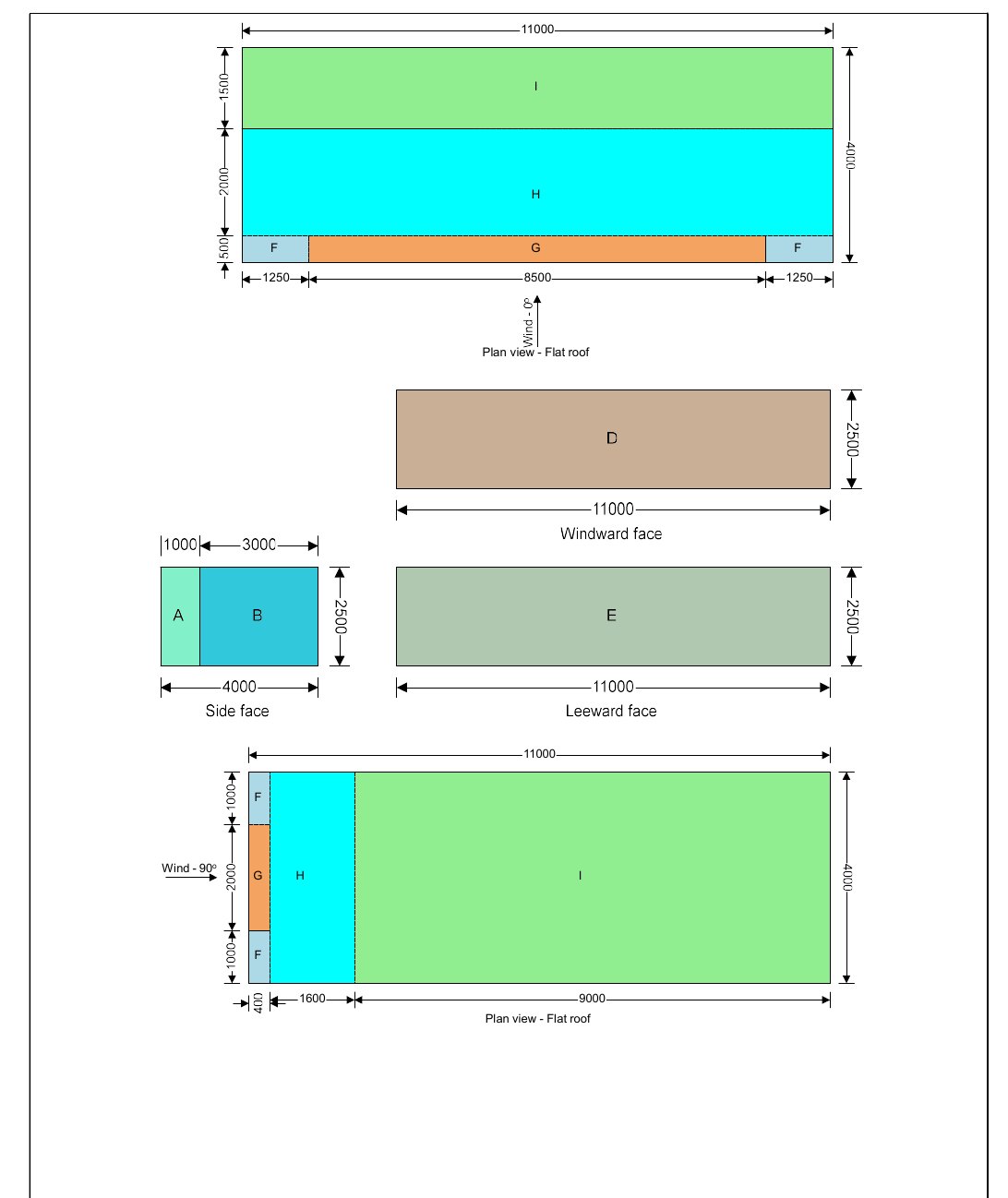
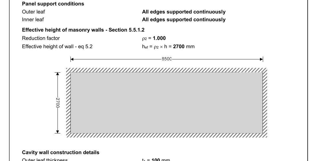
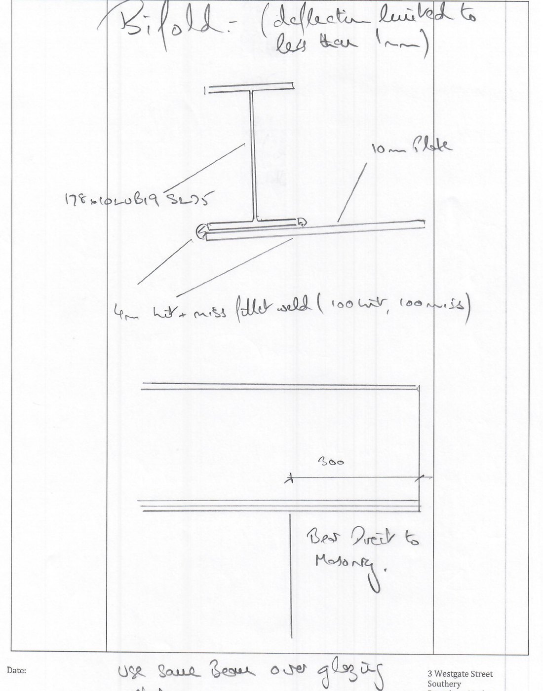
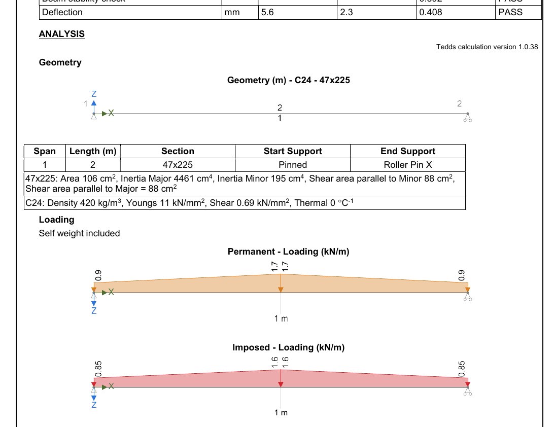
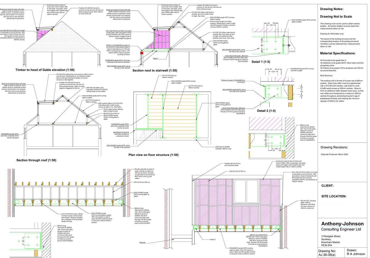
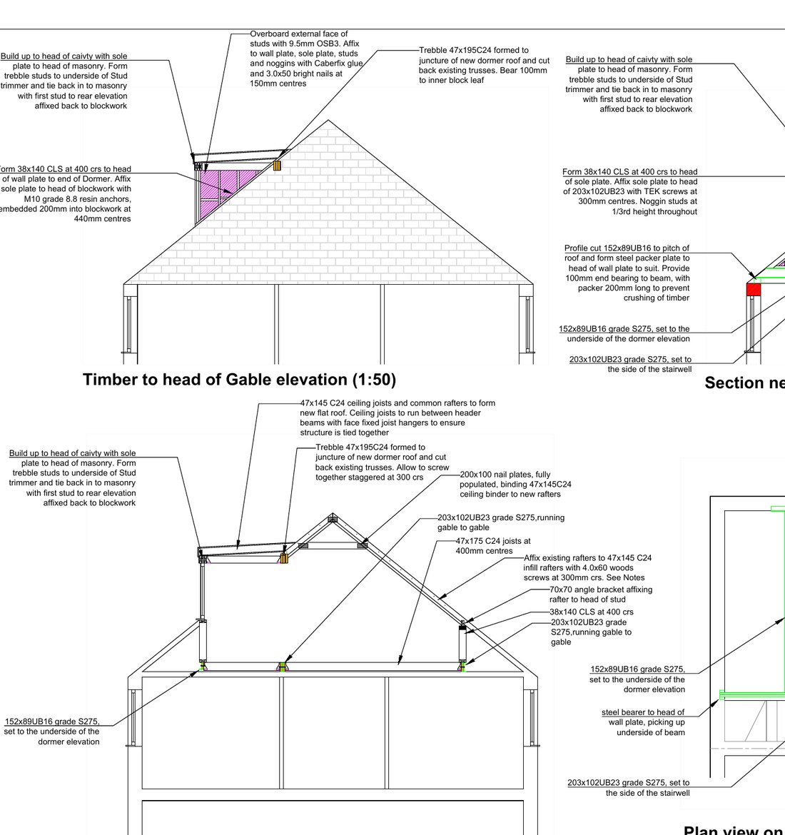
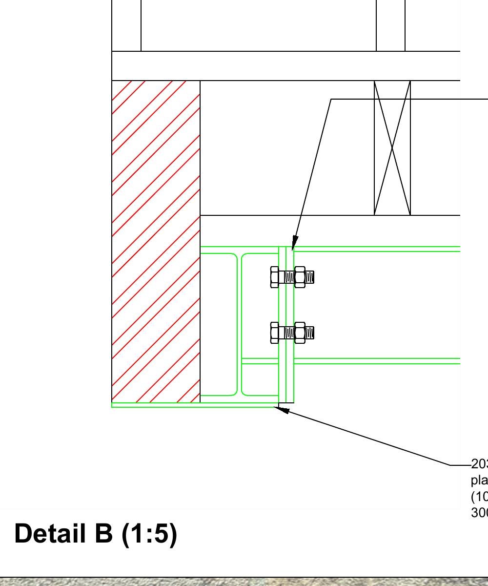
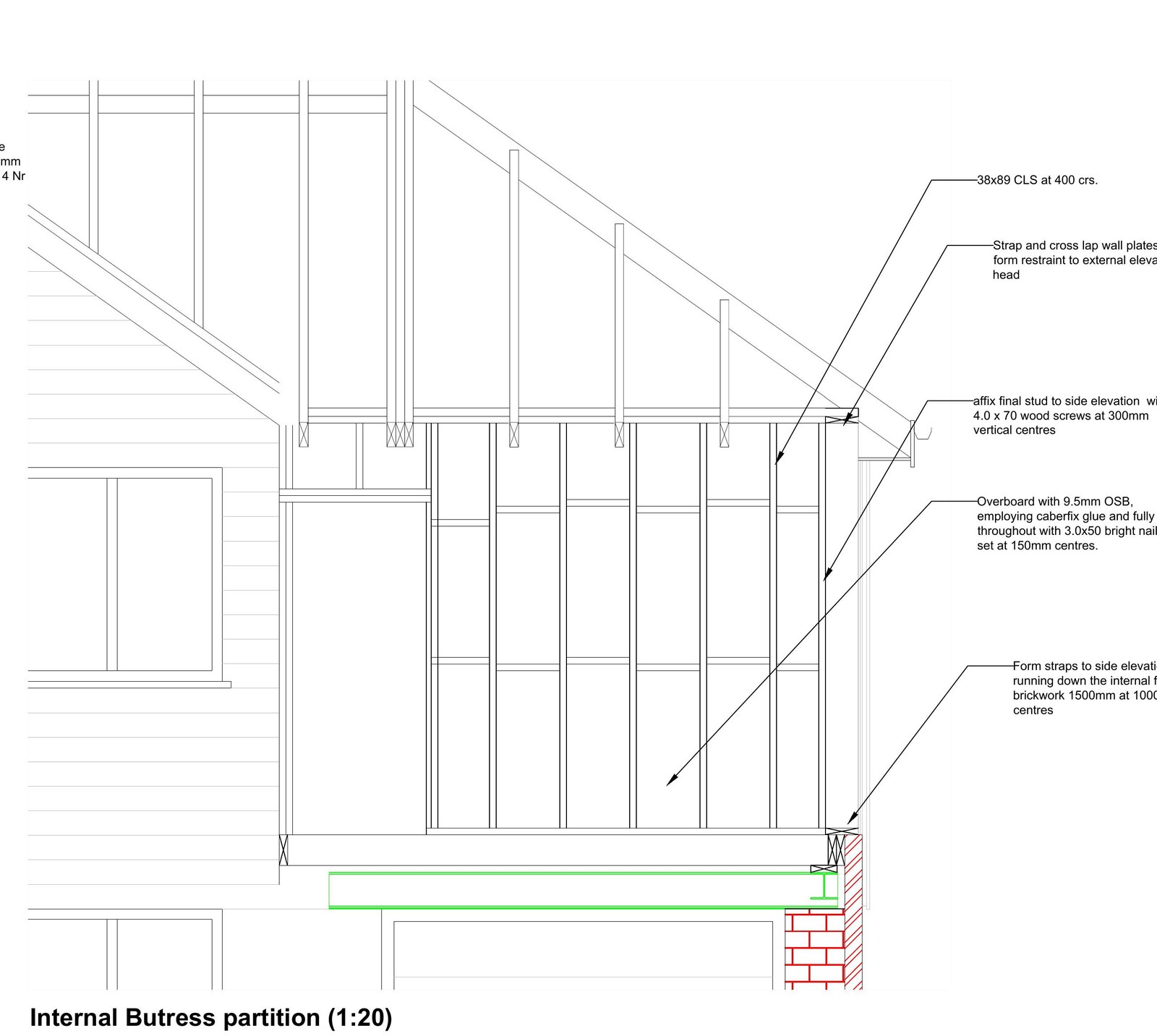
Because new foundations sat directly against the boundary, a standard strip footing risked undermining the neighbouring wall. A stepped cantilever foundation was designed instead, using a deeper concrete section as a counterweight to keep the structure stable. The superstructure design covered the new flat roof, masonry leaf and a steel beam over the opening, all checked to Eurocode.

Hand-drawn cantilever foundation section detail showing reinforced stepped concrete and floor slab
Drawing — cantilever foundationStepped section · A252 mesh
Hand-drawn steel corner connection detail with plates, bolts and welds
Drawing — steel corner connection178 UB · 10mm plate · M16 8.8
Site photograph of coarse sand with silt sample held in hand
Site — coarse sand sampleBorehole spoil
Wind loading pressure-zone diagram for a flat-roof structure
Analysis — wind pressure zonesEN 1991-1-4 · UK NA
Geotechnical surveyBorehole loggingCantilever foundation Steel connection designWind & snow loadingEurocode
Project 02 — Ground investigation
St. Johns Fen End, PE14 January 2026

Foundation strategy for two extensions on shrinkable clay

A geotechnical survey for a proposed front and side extension plus a portal-framed workshop, setting founding depths against tree influence and groundwater on a soft-to-firm clay site.

Trial pits revealed a blue-grey cohesive clay with peat inclusions and a perched groundwater table entering at around 1.5 m. The clay carries a medium volume-change potential, and the plot is ringed by willow, hawthorn and leylandii — all drivers of seasonal ground movement.

Founding depths were set using the NHBC tree-and-clay tables: up to 2.4 m where leylandii sit close to the works. The workshop was given pad foundations at depth with FND2 sulphate-resisting concrete, while the residential extensions were steered away from ground-bearing slabs toward suspended floors, to accommodate long-term heave as the ground recovers from removed trees.

Site photograph of extracted ground sample with gravel and sand
Site — extracted ground sampleTrial pit spoil
Masonry cavity wall panel diagram under lateral wind load
Analysis — masonry wall panelEN 1996-1-1 · cavity wall
Trial pittingClay assessmentNHBC tree depths Heave protectionPad & raft optionsFND2 concrete
Project 03 — Steelwork detailing
North Wootton, King's Lynn January 2026

Steel beam over bi-fold opening with deflection control

Connection and beam detailing for a wide glazed opening, where deflection had to be held below the tolerance of a bi-fold door while carrying roof and timber-lantern loads above.

Bi-fold doors are unforgiving of movement, so the supporting steel was sized for a deflection limit of under 1 mm rather than strength alone. A 178 UB with a welded bottom plate was detailed, with the connection arranged to bear cleanly onto the masonry and the secondary timber lantern trimmers framing in above.

The package included the timber trimmer design for the roof lantern and the bolt, plate and weld specification for the steel — every member checked to the relevant Eurocode and issued as buildable details.

Hand-drawn steel beam detail over a bi-fold opening with bottom plate and weld notes
Drawing — beam over bi-fold178 UB · 10mm plate · ≤1mm defl.
Timber beam analysis showing moment, shear and deflection envelopes
Analysis — timber trimmerC24 47×225 · EN 1995-1-1
Steel beam designDeflection controlWelded connections Timber lantern trimmersBuildable details
Project 04 — Loft conversion
West Lynn, PE34 March 2026

Dormer loft conversion with steel and timber framing

A full structural drawing package for a dormer loft conversion — steel beams gable-to-gable, a new dormer roof framed into cut-back trusses, and a suspended floor structure, issued as buildable CAD details.

Converting the loft meant opening up an existing trussed roof and carrying the new floor and dormer over the rooms below. A grid of 203×102 UB and 152×89 UB steels in grade S275 was arranged gable-to-gable and around the stairwell, with knife-plate and welded connections detailed bolt-by-bolt for the steel fabricator.

The existing trusses were supplemented with new C24 rafters at 300 mm centres to prevent long-term sag, and the dormer was framed in studwork tied back to the masonry. The package set out every member, fixing, weld and resin anchor — from the floor joists down to the spreader plates that stop the steel crushing the timber wall plates.

Full structural CAD drawing sheet for a dormer loft conversion showing sections, plan and connection details
Drawing — full structural sheetAJ 26-39(a) · sections & details
CAD section through the new dormer roof showing steel and timber framing with member annotations
Drawing — dormer roof section1:50 · S275 steel · C24 timber
Loft conversionSteel beam layoutWelded & bolted connections Dormer framingTruss strengtheningFull CAD package
Project 05 — Garage conversion
Murrow, Wisbech, PE13 March 2026

Garage conversion with steel-framed first floor over

A full structural drawing package converting a single-skin garage to habitable space and carrying a new first floor above — steel beam grid, suspended timber floor and a stud buttress partition, issued as buildable CAD details.

The existing garage was a single-skin brick structure on shallow strip footings, set with the head of concrete some 675 mm below ground. Trial pitting exposed those footings so new Gen 3 concrete foundations could be trench-filled down to the same depth and tied back to the existing masonry, giving the converted structure a sound base before the new floor was carried over.

Above, a grid of 203×102 UB, 152×89 UB and 152×152 UC steels in grade S275 was arranged to pick up a new suspended floor of 47×175 C24 joists at 400 mm centres, with the beams bearing 300 mm into masonry or onto welded UERSA bearers. Every connection was detailed bolt-by-bolt — 10 mm end and side plates, 4 No. M16 grade 8.8 bolts and 6 mm fillet welds — and a stud buttress partition off 7.3 Newton blockwork was strapped back to the side elevation to restrain the external wall.

Full structural CAD drawing sheet for a garage conversion showing first floor plan, connection details and footing section
Drawing — full structural sheetAJ 26-39(b) · plan & details
CAD steel connection detail showing end plate, side plate, bolts and fillet welds
Drawing — steel connection (Detail B)10mm plate · M16 8.8 · 6mm weld
Site photograph of an exposed existing garage footing in a trial pit
Site — existing garage footingsTrial pit · Gen 3 trench-fill
CAD section through an internal buttress stud partition with restraint straps to the external brickwork
Drawing — buttress partition38×89 CLS · 9.5mm OSB · straps
Garage conversionTrench-fill foundationsSteel beam grid Suspended timber floorWelded & bolted connectionsButtress partition

Drawings, photographs and calculation figures shown here are extracts from issued design packages and remain the copyright of Anthony Johnson Consulting Engineer Ltd. Project locations are shown at a general level; full reports are confidential to the instructing clients.

Your project

Have a scheme that needs this kind of work?

From a single beam to a full ground investigation and foundation design — get in touch to discuss what your project needs.